Optical Tweezers
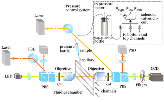
The basic elements in an optical tweezers instrument can be grouped into those common to an optical microscope and those related to the generation of the optical trap. The microscope elements are an objective, a fluidics chamber and a condenser lens. The trap elements are a laser and a photodetector that registers the light at the exit of the condenser. To produce a strongly focused beam, a high-numerical aperture objective is required. Near-infrared lasers are optimal for manipulating biological structures, because neither water nor biological structures strongly absorb radiation at this wavelength. Laser power in the focal region of several hundred milliwatts provides a good balance that prevents photodamage and produces forces up to a few hundreds of piconewtons.
The near-infrared radiation does not damage biological samples, but can alter its normal operation. Then, to decrease the amount of energy reaching the focal region, we set up a dual-beam system, in which two counter-propagating laser beams converge to the same foci. This dual trap has two additional advantages: it provides a very high trapping efficiency in the axial direction (the scattering forces of the opposing laser beams are cancelled out) and it avoids the loss of most of the marginal scattered rays enabling the force calibration by the principle of momentum conservation.
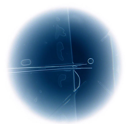
The microfluidics chamber is the test tube for mechano-chemical assays. Buffers can be easily exchanged and flowed at a controlled rate, thus adding the ability to exert hydrodynamic pressure. A micropipette can be placed inside the chamber to suck beads and additional tubes can be used to dispense chemicals (for example, ATP) directly to the vicinity of the optical trap. Our instrument thus allows experiments in physiological conditions.

Scheme of our dual-beam optical-tweezers setup (not to scale), based on Smith et al., Methods Enzymol. 361:134-162, 2003. Two 835-nm diode lasers are used to generate the optical trap in the interior of a microfluidics chamber. A blue LED is used to illuminate the sample in Köhler configuration. A pressure system is used to control the flow speed (typically, ∼1 μL/s) of the sample solution in the microfluidics chamber.
Go to MiniTweezers
Go to AFM


TECHNIQUES
HISTORY & GALLERY
Optical Trapping
It was known from physics and the early history of optics that light carries linear and angular momentum, and therefore exerts radiation pressure and torques on physical objects. However, its strength was not recognized until recently to be large enough for practical uses. With the advent of laser radiation, Arthur Ashkin showed, in 1970, that one could use the radiation pressure from laser beams to significantly affect the dynamics of small transparent micro and nanometer sized neutral particles. In 1986, A. Ashkin and S. Chu managed the trapping of neutral particles with a focused laser beam, giving birth to the optical tweezers technique and enabling the optical manipulation of atoms, molecules, cells and nanoparticles.
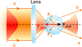
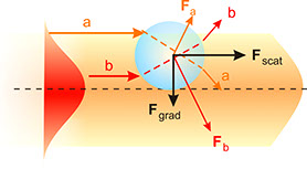
A laser can be viewed for many purposes as a gun, shooting photons in almost linear trajectories. These light bullets go through the physical objects pushing or modifying their trajectories in complex ways. By focusing the light rays it is possible to trap a neutral particle in three dimensions. More in depth, the total force on a particle can be split into two main components: the scattering force, which pushes the particle along the incident beam, and the gradient force, which points towards the centerline of the beam and is responsible for the trapping.
Optical forces on a neutral sphere. Left diagram illustrates the origin of the scattering and gradient components of the optical force. Right diagram shows the axial stability generated by the gradient force along the centerline of the beam, towards the focal region.


Español
Universitat Politècnica de València Camino de Vera, s/n 46022 Valencia Dr. J. Ricardo Arias-Gonzalez

